Pressure Vessel Design Calculations as per ASME BPVC - Section VIII Division 1. Understand the design and calculation process for NonStandard Flanges and at the same time identify the keys of a good design.

Flange Stress Analysis
Read customer reviews find best sellers.
. I use Taylor Forge as a go-by for flange greater than 60. ULMA has designed flanges of up to 102 inches in diameter meaning an internal pipe diameter of 26 metres. Materials of Construction and Allowable Stress Values 3.
ASME B165 Flanges PT Ratings. The large database is available at the hands of designer and user friendly environment created by dialog control language boxes of the program makes the. Check all the express courses of the PRESSURE VESSELS SERIES.
1 For flanges with flat gaskets it is necessary to calculate the flange equivalent calculation pressure according to the requirements of HGT20582 and then select the appropriate flange. Flanges for extremely high pressure applications. Fabrication and Welding 6.
Crotch plated 90 degree double tees or crosses. The flange calculator includes a database of 600. Welcome to this interactive flange bolting calculator from HYTORCThe program computes recommended torque values bolting patterns tool selection and pump pressure settings for standard ASME B165 and API 6A flanges under normal assembly conditions.
In this example we look at a complex piping system of a mineral processing plant that included following non standard fittings. API ANSI BS and MSS standard pipeline and piping flanges ranging from ½ inch to 48 inch and an independent. Waters method is established on the basis of online elastic plate and shell theory of non-standard flange design calculation method whether it is internal pressure flange or external pressure flange in addition to the flange moment calculation formula is different according to the flange ring and cylinder or including tapered neck connected to the degree of.
The output Drawings can be exported in any format supported by AutoCAD. Crotch plated 45 degree lateral tees. Non-standardised pipe dimensions high external stress etc.
By Abdel Halim Galala in forum Engineering Spreadsheets Presentations. A computer code for Mechanical and Drafting Design of Non standard flanges is developed in Auto LISP compatible with AutoCAD. Wangzh2k you most assuredly can design a non-standard flange with Appendix 2.
ULMA can also supply special and non-standard flanges design calculation manufacturing and testing and critical joints SUBSEA that guarantee the integrity utility and durability of the flange joint. Allowable stress at atmospheric temp. Ad Shop Our Exclusive Collection of Pipe Flanges Online.
Large pipe diameters. In this course you will learn. Texas Flange has been in the business of prec.
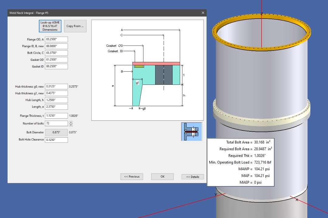
Non-standard flanges are designed and calculated according to ASME VIII Div1 Appendix 2 and Appendix S and according to ASME VIII Div2 part 416. Equivalent flange pressure due to ext. FsubL factor for loose-type flanges.
Non-standard flanges are designed and calculated according to ASME VIII Div1 Appendix 2 and Appendix S and according to ASME VIII Div2 part 416. Ad We provide ANSI API and AWWA pipe flanges in carbon steel stainless steel alloys. Free shipping on qualified orders.
Free Shipping on Orders Over 99. Determination of foming strains. Since I have designed many non-standard flanges from 60 to 120 for pressure vessels the starting point is to pick a similar flange dimensions and be proportional to it.
Non standard ASME Flange Design Calculations Excel sheet for Pressure Vessel. As for your ASME no longer ANSI standard flanges while I am not sure of the exact reasons it is well known these do not meet Appendix 2 design. Forming strain of a cylinder.
Ad Browse discover thousands of brands. The most common non-standard characteristics are. 2 For the design of non-standard flanges without flat gaskets the influence of external loads on bolts and flange moments can be dealt with based on ASME VIm-2 2019.
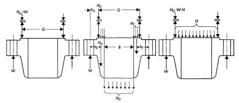
ASME Flange Design Calculations. Flange Calculations for Non-Standard Flanges 5. The principal design code for the establishment of pipeline and piping flange stresses is ASME VIII Division 1 Appendices 2 P and S which forms the basis for the calculations in the flanges calculator.
Were here to help with your flange needs. Process of design and calculation of different nozzle configurations and their main components. Free easy returns on millions of items.
32 Bolt characteristics This area displays. I believe that at least part of the reason is they are typically much over-bolted compared to Appendix 2 design. For flanges without flat gaskets determine the maximum allowable working pressure of the flange when there is an external load equivalent to increasing the maximum allowable working.
Gasket OD 1775 Gasket ID 1625 Gasket m 3 Gasket y 10000. Decide gasket type and dimensions in advance. Torque calculations are based on the simplified formula explained in the current.
The above fittings can have many variants like equal unequal non reinforced pad reinforced or integrally reinforced. ASME B165 flanges external loads - UG-44 b Loose-type flange under internal pressure.
Appendix 2 Asme B16 5 16 47 Flange Design Codeware

Bn Ds A11 Design Standard Flanges For Nonpressure Piping Connections

Flange Calculations According To En 1591 1 Youtube

Non Standard Flange Design And Bolt Tightening Basis Video1 Youtube

Design Of Lap Joint Flange Www Steeljrv Com
Non Standard Flanges Asme Viii Arveng Training Engineering
Appendix 2 Asme B16 5 16 47 Flange Design Codeware

11 How To Design Nonstandard Flanges On Standard Nozzles Autopipe Wiki Autopipe Bentley Communities
0 comments
Post a Comment